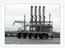
CUPROBAN Impressed Current Cathodic Protection Systems for Marine applications
The Principle of Cathodic Protection
All metals and alloys undergo a natural process of corrosion depending on the metal and the surrounding environment. Metal atoms have loosely bonded electrons which they tend to lose. When a metal is immersed in an electrolyte such as sea-water this tendency results in the setting up of an electric potential. The loss of electrons from the metal leads to its dissolution or corrosion.
Further if two dissimilar metals are electrically in contact and immersed in the same electrolyte, the more reactive (or baser) metal will part with its electrons more readily and will corrode in preference to the less reactive (or nobler) metal. The surface or material where loss of electrons and hence corrosion takes place is called the anode and the surface where electrons are absorbed and where there is no corrosion is called the cathode.
Even in a seemingly uniform single metal structure (for instance a ship’s hull or the legs of an off shore platform) there will be enough metallic dissimilarities to create internal anode anodic and Cathodic spots on the surface leading to corrosion. In a painted surface if there is a small area where the paint has deteriorated that area will become anodic with reference to its neighbouring areas leading to corrosion. If there are bi-metallic connections – for example the hull of a ship is steel while the propellers are bronze (a metal that is Cathodic to steel) – anodes and cathodes are automatically created leading to corrosion.
In summary, corrosion can thus be seen to be an electro-chemical phenomenon. Its prevention by cathodic protection is also an electro-chemical process. The principle of cathodic protection is to create a potential gradient opposing the flow of electrons from the surface to be protected.
One of the methods of doing this is by using an Impressed Current Cathodic Protection System. This works on the principle that current flowing on to any metal shifts its normal potential in the negative direction and if correct amounts of current can be impressed on the surface to be protected, the potential of the surface can be shifted sufficiently to a level where the surface will not corrode.
For example, steel when submerged in sea water generally has a normal potential of -500mV to -600mV w.r.t. an Ag/AgCl reference electrode. At this potential steel corrodes. But if by impressing a current onto the surface the potential of the steel can be moved to -750mV or more negative w.r.t. an Ag/AgCl reference electrode corrosion stops and the steel is protected.
Functioning of an Impressed Current Cathodic Protection System
ICCP Systems work by taking the ship’s power, converting it using as a transformer rectifier unit into direct current and impressing this on to the hull through inert anodes strategically positioned on the hull.
The current will flow from the inert anodes through the sea water and back to the hull. This is ensured by a sufficiently large dielectric coating applied on the hull around the anode.
ICCP Systems are generally self-regulating using a feedback control system. This is done by positioning suitable Reference Electrodes at various points on the structure to measure the potential of the structure at those points. By comparing the measured potential with the desired non-corroding structure potential, the control unit of the ICCP System determines whether the current feed to the hull through the anodes should be increased, decreased or maintained. The objective is to ensure that the potential of the structure as measured by the Reference Electrodes is as close to the desired protection potential as possible.
Advantages of an ICCP System
- Carefully designed ICCP Systems can compensate for a fair amount of coating damage and help extend dry-docking intervals.
- There are typically no anode removals required during the dry-docks unlike in the case of Sacrificial Anode system and hence, maintenance costs are reduced.
- The instrumentation on the ICCP control panels enables the protection levels to be continuously monitored.
- The ICCP anodes are generally flush mounted on the hull or even if surface mounted are very few in number thereby reducing structural loading as compared to sacrificial anode and providing significantly less hydrostatic and hydrodynamic resistance, thereby reducing fuel consumption of the ship.
The CUPROBAN ICCP System
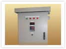
CUPROBAN makes a range of ICCP Systems from 25-amps to 400-amps. The control panels are offered in a range of sophistication from simple linear systems to advanced systems using high frequency power supplies enabling individual anode current control. Features such as automatic data logging, remote display, etc are also available in different models of control panels. The panels are rugged and typically meet IP54 requirements offering almost maintenance free and long lasting protection.
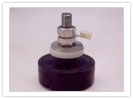
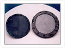
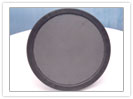
CUPROBAN offers MMO-coated Titanium anodes in the form of disk anodes, elliptical anodes and linear anodes capable of handling currents from 25-amps to 175-amps. These anodes typically have lives of 15 to 25 years and come with epoxy resin holders and in some models, with neoprene rubber holders.
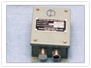
CUPROBAN also makes both Zinc as well as Ag/AgCl Reference Electrodes. The Anodes and Electrodes are supplied with rugged cofferdam assemblies. These are easy to install but at the same time are safe having been pressure tested.
|
|